

How To Control Camera On Phantom 4
Have you wondered what is inside the Phantom 4 torso? Always since the Phantom 4 landed in our office, the engineers take wanted to take a look inside the quadcopter, curious to find out 'what'south improved this time?'. By now nosotros had all seen the most-advanced-technology video on the DJI Youtube channel. Released as part of the production launch it gave a height level insight into what goes on within the new Phantom. We wanted to go past the 3D 'exploded blitheness' and discover only how difficult it would exist to service or repair the drone.
Please note : This is not intended to be an instructive guide (such every bit those constitute on ifixit) for dismantling your drone, just more a documentation of our investigation into the architecture of the new quadcopter. Nosotros take no responsibility for any potentially warranty-invalidating work carried out on your Phantom by yourself, information technology is at your own risk.
Tools required

- 2mm Hex Driver
- 1.5mm Hex Driver
- Pocket-size Cross-caput
- Pocket-size flathead
- Plastic spudger
- Trim removal tool
Teardown : Dismantling the Phantom 4
The major difference this teardown revealed is that unlike previous Phantom'southward, the Phantom iv has all its hardware connected to the 'lid' of the trounce; Acquit this in mind when removing it. To commencement we've put together this diagram showing the location and size of the bolts on the outside of the craft.  As per previous models, the photographic camera and gimbal are one unit and we'd recommend get-go here (once you lot take removed the battery). The gimbal is held on by 8x 1.5mm hex screws on the light grey blended belly of the craft (labelled in blue in a higher place). When these have been removed, run a plastic tool around the edge of the gimbal plate to release the clips that retain it. You tin come across the locations in the photograph beneath.
 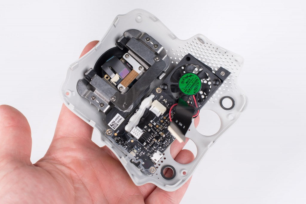 Carefully lower the camera and gimbal and undo the 2 ribbon cables (one of a lever type) that connect it to the flight controller board. This tin can now be moved out of the way. With the gimbal removed y'all tin can admission the cross head screws on white tabs property the composite internal frame to the lower vanquish. Adjacent at that place are eight hex screws, one at the arm/trunk transition and ane half way downwardly each arm. They are marked in ruby on the initial diagram.
  The plastic light diffuser (as seen in the above photo) on the arm under each motor simply pop off with a flat head screwdriver. At that place is a pocket-sized slice of white card taped down as a reflector for the LED, remove this and reveal a further 3x 2mm hex bolts per arm. With all of these removed, run a plastic tool around the seam in the upper shell, releasing each of the clips as you become. Take your time every bit to non harm these.
  Unplug the 2 grey compass cables and remove all iv of the button-on antenna connections for the lightbridge.
  Finally the unabridged peak one-half of the craft lifts off taking the internal chassis and electronics with it, leaving the compass and antenna in the legs below. The teardown continues from hither, disconnecting the cables and ribbons from the ability and speed controller boards to the main section, unscrewing them from the core before unscrewing the core itself from the top shell to advisedly remove it.
  The main processing board sits on the bottom of the composite core, cooled by a big heatsink and the fan in the gimbal. The flight controller is stacked with the logging SD bill of fare visible.
  The leading edge of the cadre has mounts for the front visual sensors, connected to the board via ribbon cables.
  The blended core likewise features the lower VPS visual and ultrasonic sensors for vertical altitude calculations.
Lower vanquish, Landing gear and Antenna
The lower vanquish is made of lightweight plastic and houses the antennas and compass in the legs, running the wires internally.  On the underside you can encounter the full length foam safe landing pads with markers to assistance installation of the gimbal.
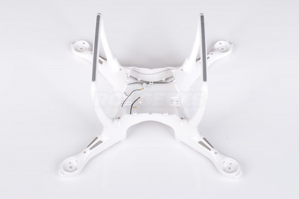
Motors and Mounting
 Motors are located on a set of posts, locating them before the torso screws agree them in place.
  Motor and LED cables run the length of the arms below the upper instance.
  The lower shell slots onto the upper shell shown in the previous photo
New ESC (Electronic Speed controllers)
The phantom 4 features all new speed controllers. The boards are mounted vertically, screwing into the sides of the magnesium core. Each ESC controls a pair of motors (1 CW and one CCW) a pair of LED's and has a power feed to the main distribution lath.  A ribbon cable from the flight controller feeds the command information to each lath, you lot can run across the connector on the top leading edge.
Ability distribution and Bombardment connector
The ability distribution board now sits at the front of the drone with twin outputs.  The daughter boards are fed via plugs on its edge and a ribbon control cable pictured on the right in the image beneath.
  The battery connector has (thankfully) been totally redesigned from all of the previous phantoms. It is at present a 10 pin plug with metal surround protecting it. Externally it makes charging the battery easier every bit its reversible. Internally in that location is much less chance of the battery becoming disconnected during flight compared to the sprung pins.
  The top of the torso is lined with soft padding and copper insulation film protecting the GLONAS/GPS module that lives in the lid.
  Bombardment installed without composite internal frame to demonstrate location.
  The bombardment has a set up of guides molded into its casing that line upwardly with markers on the blended cadre.
  Bombardment removed from the upper trunk and placed bated for calibration.
New Gimbal/Camera mount and electronics
The passive dampening of the gimbal has been moved into the craft, allowing for a cleaner more aerodynamic contour externally. The new gimbal damper employs a series of bushing materials to cushion its motility and appears a lot hardier than the previous rubber dampers.  Internally a modest fan blows air through the perforated lesser plate over the heat sink on the core. The board itself is continued to the rest of the electronics via two ribbon cables.
  On the exterior the new gimbal mountain is beautifully designed out of matt finished plastic.
  The gimbal itself has been upgraded with dual motors for the tilt axis, this secondary mounting point volition potentially reduce shake.
Teardown component overview
 The frame components laid out in order.
  Overall we experience that it is slightly more involved than deconstructing the Phantom 2/3, due to the well-packaged design.
  Farther information virtually the Phantom iv, or to place an society, bank check-out the Phantom iv Quadcopter on our website. If you have crashed or damaged your drone, please make it contact with us here and nosotros will endeavor to assist. Full details of our Phantom and Inspire 1 repair service will be released later this calendar month. If y'all have any questions regarding this bones teardown, or require any further images delight leave a comment beneath.
Source: https://www.rcgeeks.co.uk/blogs/news/phantom-4-basic-teardown-whats-inside
Posted by: yusomearesove.blogspot.com
0 Response to "How To Control Camera On Phantom 4"
Post a Comment